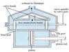
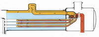
As
the exhaust steam travels from the cylinders and through the smokebox
to the chimney, it creates a draught which draws the smoke and gases
from the firebox and boiler tubes and also pulls fresh air through the
firegrate. The harder the engine is worked, the more steam is used,
which in turn means a bigger draught and a hotter fire that leads to
faster steam production.
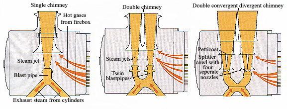
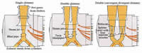
The used steam from
the cylinders is ejected from the blastpipe, which is a nozzle at the
bottom of the smokebox facing the chimney mouth.
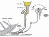
Up to a point, the
smaller the nozzle the greater the speed of the steam and the stronger
the draught, however, this creates a draught that is uneven and tends
to draw out pieces of half-burned coal with the smoke from the fire. In
addition, a small nozzle creates back pressure in the cylinder because
the used steam cannot escape fast enough. An ideal blast is strong but
slow and steady, and provides a fast passage for the steam leaving the
cylinders.
Because the strength
of the draught through the firebox and boiler tubes is directly related
to both the used steam velocity and the total area of the steam jet in
contact with the gases in the smokebox, it is possible to improve the
draught by altering the design of the nozzle in the blastpipe.
The simplest and
easiest method to improve draughting is to have two blastpipes, each
exhausting through a different orifice in a double chimney. This design
was favoured by the L.M.S. Railway where it produced a startling
improvement in the performance of the Royal Scot class of locomotives.
Similarly, after nationalisation, this design was applied to the GWR
King and Castle classes with equally noticeable improvements.
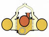
Probably the most
advanced method of draught improvement was with the Kylchap design,
perfected by the French engineer Andre Chapelon. This had two
blastpipes, but each nozzle formed a cross-section of four circles
joining in the centre, so that the steam emerged as four jets that met
in the middle. Beneath each chimney orifice were two petticoat pipes,
shaped to split the four jets and then combine them again as a single
jet that was exhausted through the chimney.
Locomotives that were
fitted with the Kylchap exhausts were noted for their exceptionally
free running. The exhaust from the chimney was so soft that
non-streamlined engines required deflector plates to lift the smoke
away from cab windows. |