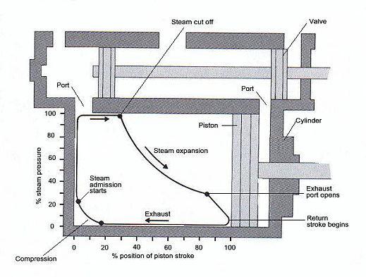
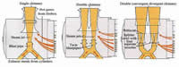
When a steam locomotive was tested for its efficiency under all working conditions , indicator diagrams were drawn showing in graphic form what takes place inside the cylinder. These diagrams made it possible to measure the efficiency of converting the steam's energy into mechanical energy within the cylinder at various speeds and cut-offs.
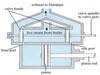
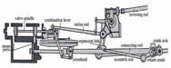
Testing indicators, consisting of a special pressure gauge with the means to present the readings in a diagram, were fitted inside the front and rear cylinder covers. Throughout most of the steam era, mechanical indicators were used but electrical indicators were tried in the pot-war period.
With the mechanical indicators, the diagram was drawn at the cylinder and this required the attendance of engineers riding on the buffer beam. To protect the from the elements, screens were erected around the front of the locomotive but these merely added to the technicians discomfort, as they had to perform their task on a bucking engine, with penetrating winds on one side and a hot smokebox on the other. The engineers advised the dynamometer car staff behind the tender, when an indicator reading was taken by means of a speaking tube or bell so that marks could be made on the paper roll recording the pull on the drawbar. From these readings, a graph could be obtained.
Electrical indicators were introduced from equipment developed to measure pressures inside aero-engines, and had the added advantage that their readings were passed directly to the dynamometer car. This design of the recorder was ingenious as it dispensed with the pen used in mechanical indicators. It emitted a spark when the steam pressure within the cylinder reached a certain level, which burned a small hole in the recording paper. After several cycles of steam entry, expansion and exhaust, the sparks had traced a series of holes.
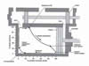
Whatever the type of indicator, the resulting diagram was always in the shape of a boot. The highest part shows the pressure as the steam entered the cylinder as shown by the top horizontal line, but when the steam entry is cut off, the pressure falls as the steam expands and pushes against the piston. After the exhaust port opens, the line, like the piston, reverses and shows low pressure as the used steam is exhausted. At the end of the return stroke the line rises as pressure increases due to the compression caused by the remaining steam left in the cylinder after the exhaust port has closed. As fresh steam is admitted into the cylinder, the pressure rises once again. |